The electronic system diagram represents a starting point for the development of an electronic system.
Prior to this system design, it was established that there was a need for a computer controller with memory.
The computer controller requires an interface, with inputs from sensors.
IR range finders, rate gyros and tacometers were chosen as sensors following an early brainstorming session and much research.
A Personal Data Assistant was determined to be a promising controller.
Book Reference: PDA Robotics. (Thanks to Pembroke College Library).
An HP iPAQ was chosen but found not to have a USB host.
A Balloon Board is currently being considered.
A complete system solution is provided by the National Instruments Compact RIO product line and has been considered.
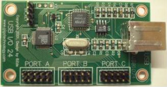
USB I/O 24 card:
Bandwidth Budget 8/11/4:
| Component | Samples/s | Bits | Quantity | Bandwidth |
| IR range finder ADC | 4760 | 1 | 1 | 4760 |
| Gyros ADC | 3060 | 1 | 1 | 3060 |
| IR tacometers | 1600 | 1 | 4 | 6400 |
| Radio PWM receiver | 256000 | 1 | 2 | 512000 |
| ESC PWM outputs | 256000 | 1 | 2 | 512000 |
| IR range finder ADC clock | 4760 | 1 | 1 | 4760 |
| Gyro ADC clock | 3060 | 1 | 1 | 3060 |
| TOTAL: | 1046040 |
This budget prompted a meeting with Peter Long and consideration of alternatives to direct PWM.
Infra-red range finders:
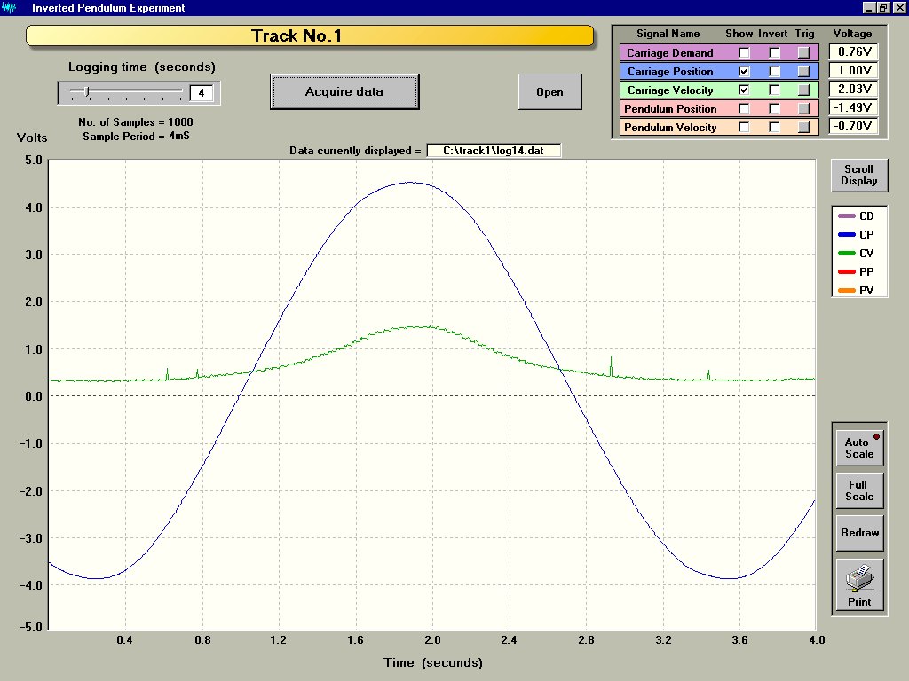
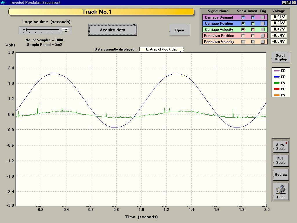
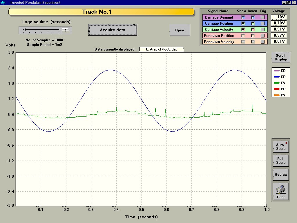
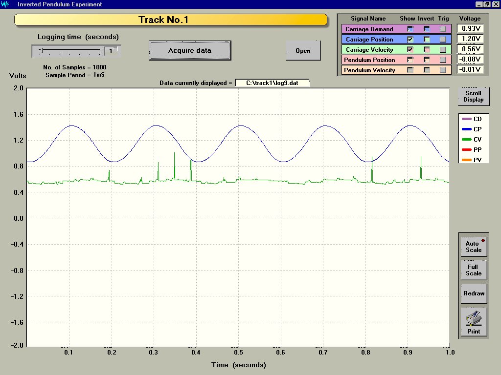
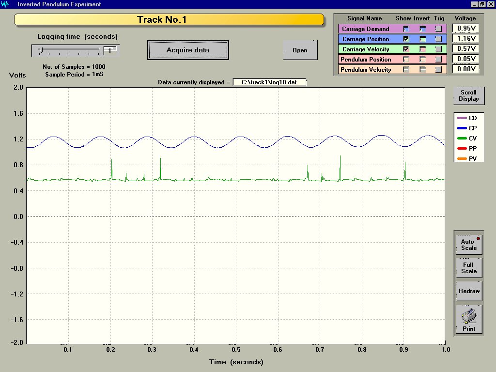
We have conducted tests on our preferred IR range finder using CUED's Inverted Pendulum experiment apparatus (thanks to Dave Gautrey).
The results both take the form of screenshots of the graphing software and text files containing data for analysis.
The full range of the sensors is 20cm to 80cm. The critical range for the unicycle's geometry is 36.5cm to 51cm.
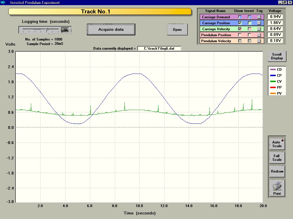
20cm to 80cm range Sine Wave dataset 1: Screenshot Data
20cm to 80cm range Sine Wave dataset 2: Screenshot Data
20cm to 80cm range Triangle Wave dataset 1: Screenshot Data
20cm to 80cm range Triangle Wave dataset 2: Screenshot Data
36.5cm to 51cm range Sine Wave 0.1Hz: Screenshot Data
36.5cm to 51cm range Triangle Wave 0.5Hz: Screenshot Data
36.5cm to 51cm range Sine Wave 1Hz: Screenshot Data
36.5cm to 51cm range Sine Wave 2Hz: Screenshot Data
43.5cm centre range Sine Wave 5Hz: Screenshot Data
43.5cm centre range Sine Wave 10Hz: Screenshot Data
Infra-red detectors (Tachometers):
Ultrasonic range finders:
Discounted as not fast enough response.
Electronic Compass:
Still under consideration due to requirements and possible interference effects.
Inclinometers:
Avoided due to slow response and interaction of lateral accelerations.
Tilt switches:
See above, but may be used to confirm attitude under low acceleration conditions.
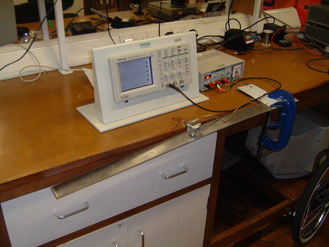
Rate Gyros:
Glen Vinnicombe in the Engineering Department has given us three Gyros:
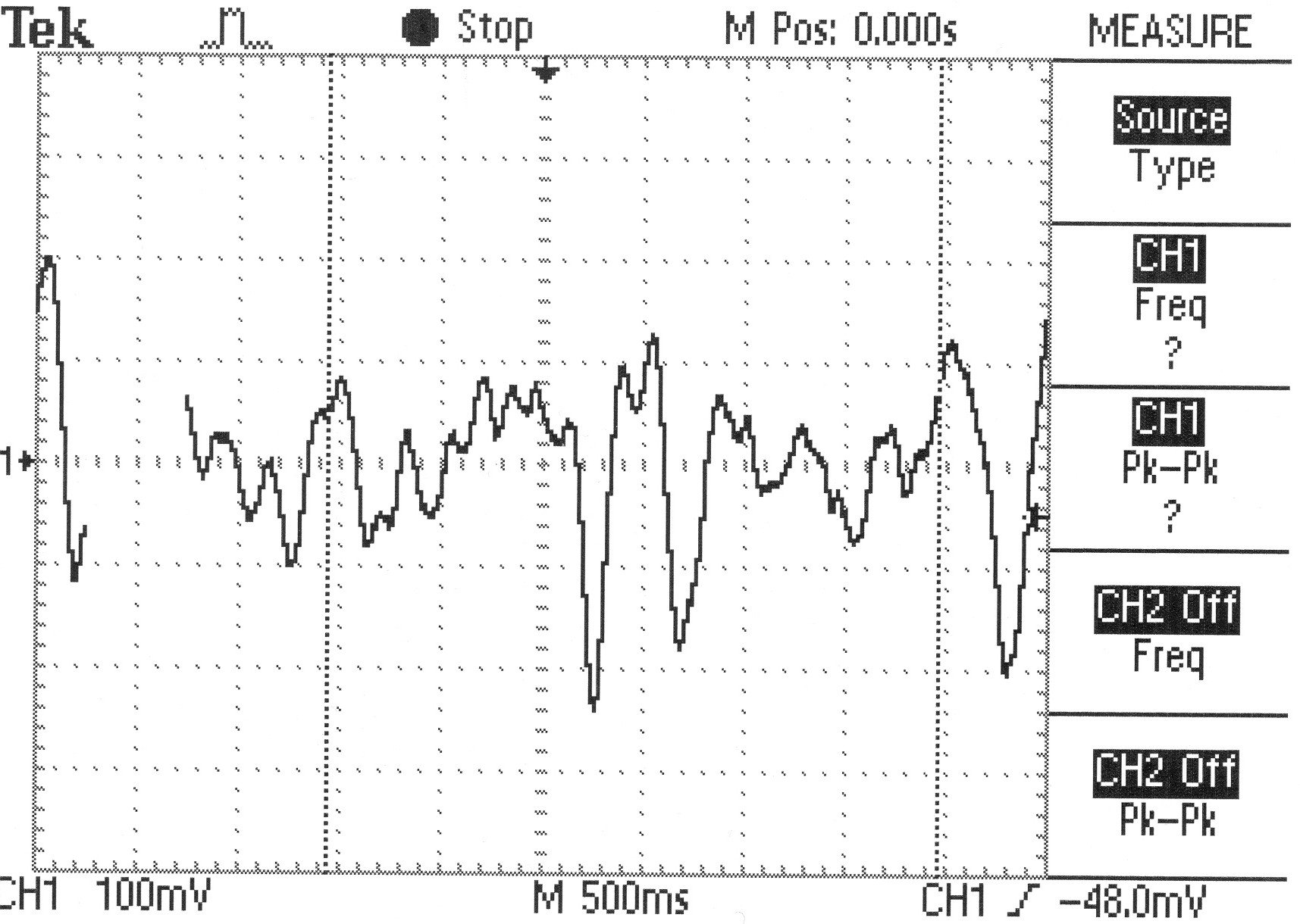
We have conducted tests to investigate the output of these gyros:
Calibration photo 1 (low frequency response)
Calibration photo 2 (high frequency response)
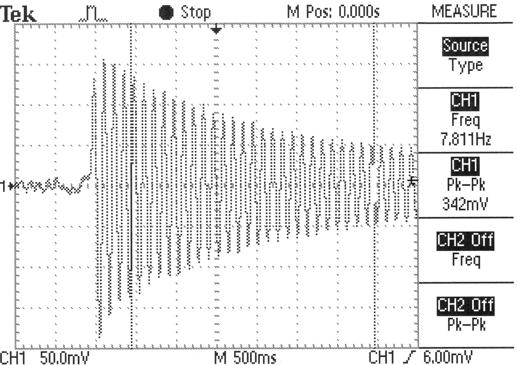
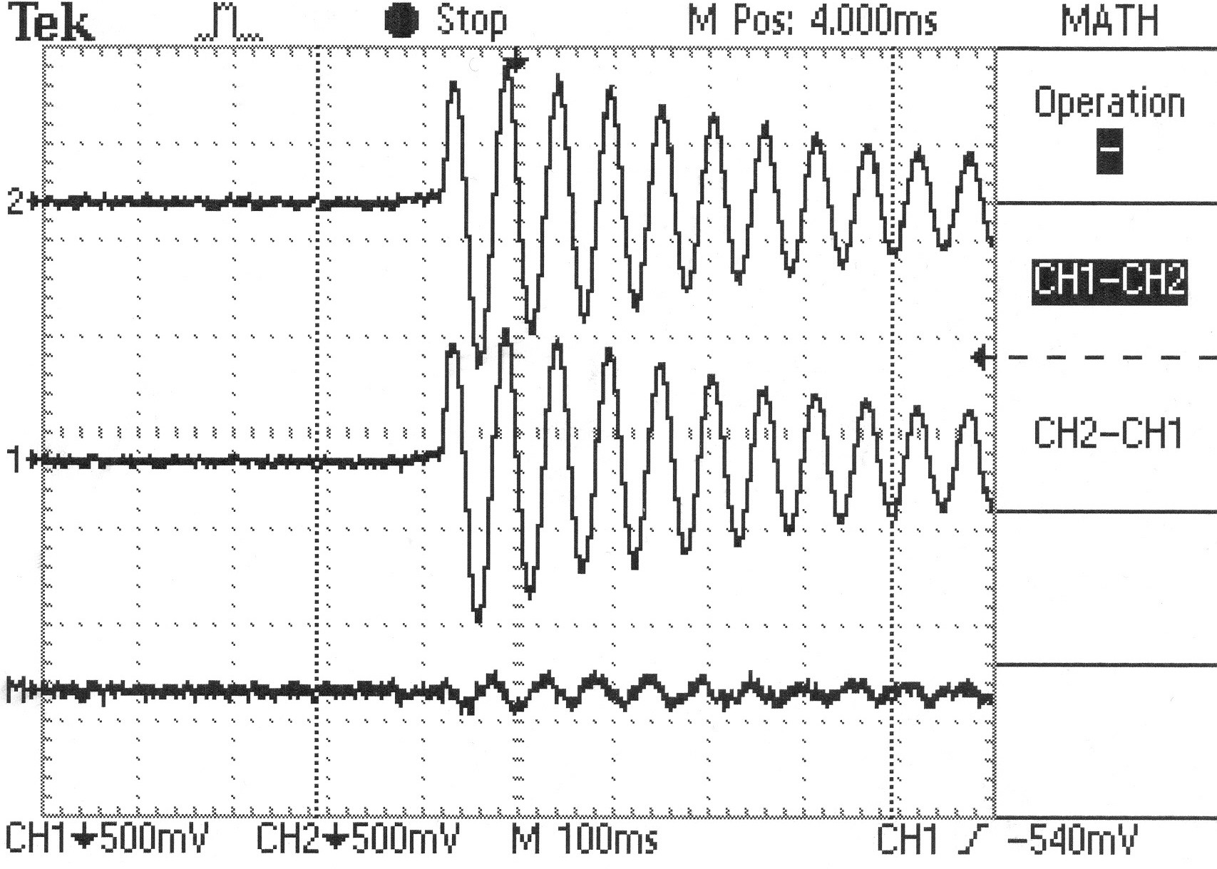
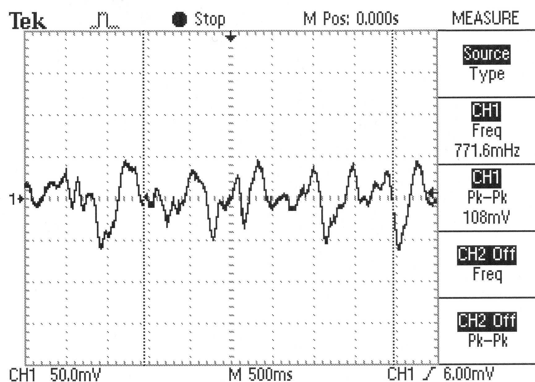
The oscilloscope plots of the tests are given here as graphics files:
preliminary test
This confirms that the gyro measures rate of change of angle and is quite reliable
fast frequency test
errors could be accounted for by saturation
slow frequency test
errors can be attributed to noise and measurement error
multifrequency test
errors could be accounted for by play in the mounting of the gyroscope when under high acceleration
Several options are available for the drive system: the connection between the computer and each of the two motors.
The image and table below summarise the characteristics of each option.
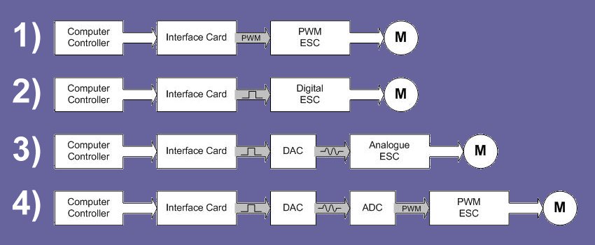
ESC = Electronic Speed Controller
| No. | Computer Controller Bandwidth | Response time | Processing | ESC Cost | Hardware | Debugging |
| 1) | Very high for PWM: 256kbps Max | 100ms | Intensive | £40 | 1 stage | Limited internal |
| 2) | Medium: 9.6kbps (RS232) | 10ms | Medium | £150 | 1 stage | Limited |
| 3) | Low: 30Hz min | 100ms stock | Minimal | £60 | 2 stages | Good (analogue) |
| 4) | Low: 30Hz min | 100ms | Minimal | £40 | 3 stages | OK (ADC) |
It was decided in a meeting that option 3) is most promising and worth investigating further.
Option 3) has been incorporated into the electronic system diagram.